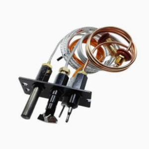
31501 RV Furnace Ignition Control Circuit Board | Atwood & Dometic Hydro Flame Compatible
$30.00
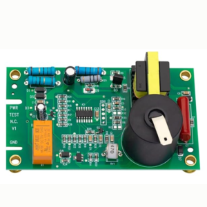
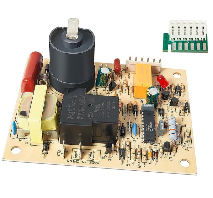
31501 RV furnace ignition control circuit board compatible with Atwood & Dometic Hydro Flame furnaces (7912-II, 85-IV, DFMD30111, DC82 25-32). 12V spark ignition, flame sensing, fan control, 3-trial ignition, 30-min lockout. Direct replacement, plug-and-play. Free shipping worldwide.
22 in stock
Free shipping on orders over $60! Delivery time: 7-12 days
- Satisfaction Guaranteed
- No Hassle Refunds
- Secure Payments
31501 RV Furnace Ignition Control Circuit Board – Atwood & Dometic Hydro Flame Compatible
The furnace ignition control circuit board is the electronic brain of your RV furnace, managing the entire heating sequence from pre-purge to post-purge. It controls the combustion fan, spark ignition, flame sensing, gas valve operation, circulation blower, and safety lockout. When the control board fails, your furnace may fail to ignite, cycle erratically, the fan may not work, or the unit may lock out completely, leaving you without heat.
This 31501 ignition control circuit board is compatible with a wide range of Atwood and Dometic Hydro Flame furnaces, including the 7912-II, 85-IV series, DFMD30111, and DC82 25-32 models. It features reliable 12V spark ignition, flame rectification sensing, fan control, 3-trial ignition with 30-minute lockout, and plug-and-play installation.
Compatibility
- Atwood Hydro Flame 7900-II series: 7912-II, 7916-II, 7920-II, 7924-II, 7932-II
- Atwood Hydro Flame 85-IV series: 8516-IV, 8520-IV, 8525-IV, 8531-IV, 8535-IV
- Atwood Hydro Flame 89-III series: 8916-III, 8920-III, 8925-III, 8930-III, 8935-III
- Atwood AFMD series: AFMD20111, AFMD25111, AFMD30111, AFMD35111
- Dometic DFMD series (rebranded Atwood): DFMD20121, DFMD25121, DFMD30121, DFMD35121
- Dometic DC82 series: DC82 25-32, DC82 16-22
- Replaces board numbers: 31501, 520820, 520814, 33488, 33727, 521099
- Most 12,000-40,000 BTU Atwood/Dometic Hydro Flame furnaces
Specifications
| Parameter | Specification |
|---|---|
| Part Number | 31501 (replaces 520820, 520814, 33488) |
| Voltage | 12V DC (10.5-15V operating range) |
| Ignition Type | Spark ignition (12V input, 15kV spark output) |
| Flame Sensing | Flame rectification (microamp current sensing) |
| Fan Control | 12V fan output, high/low speed (SPDT relay) — circulation blower |
| Combustion Fan | 12V output for draft inducer (if equipped) |
| Gas Valve Output | 12V DC, up to 2A (SPST relay) |
| Trial Ignition | 3 attempts, 8 seconds each |
| Lockout Time | 30 minutes (manual reset via power cycle) |
| Pre-Purge | 15 seconds (combustion fan on before ignition) |
| Post-Purge | 30-60 seconds (fan on after thermostat opens) |
| Connections | Pin-style connectors (PINS version) or wire leads |
| Mounting | 2 or 4 screw mounting (matches original footprint) |
| Operating Temp | -40°F to 180°F (-40°C to 82°C) |
| Protection | Reverse polarity, over-voltage, under-voltage, over-current |
| Certification | CE, RoHS, UL recognized components |
Ignition Sequence
- Call for heat: Thermostat closes, sending 12V signal to the board.
- Pre-purge: Combustion fan (draft inducer) runs for 15 seconds to clear residual gas. On some models, the circulation blower also starts.
- Trial ignition: Spark igniter activates (15kV), gas valve opens. Board attempts ignition for up to 8 seconds. Flame is sensed via flame rectification.
- Flame confirmed: If flame is detected, spark stops, gas valve stays open, circulation blower runs at selected speed.
- Retry: If no flame within 8 seconds, gas valve closes, spark stops. Board waits 30 seconds, then retries. Up to 3 attempts.
- Lockout: After 3 failed attempts, board enters 30-minute safety lockout. Manual reset required.
- Heating cycle: Furnace continues heating until thermostat opens (set temp reached).
- Post-purge: Gas valve closes, spark off. Combustion fan and circulation blower continue for 30-60 seconds to cool the heat exchanger, then shut off.
Installation Guide
- Safety first: Disconnect 12V power at the battery. Turn off propane supply. Allow the furnace to cool completely.
- Access the board: Remove the furnace exterior access panel. The control board is typically mounted near the burner assembly, behind a plastic cover. You may need to remove the furnace from its mounting for easier access on some models.
- Document connections: Take detailed photos of all wiring connections before disconnecting. Label each wire connector with tape if needed. Note the position of each connector: 12V power, thermostat, gas valve, spark igniter, flame sensor, combustion fan, circulation blower (high/low).
- Disconnect wires: Unplug all wire harness connectors from the old board.
- Remove old board: Unscrew the mounting screws (2 or 4 screws) holding the board.
- Install new board: Mount the new 31501 board in the same position. Secure with mounting screws.
- Reconnect wires: Plug all wire harness connectors into the corresponding positions (refer to your photos). Ensure all connections are secure. Double-check the 12V power connections.
- Test operation: Reconnect 12V power. Turn on propane. Set the thermostat to call for heat. Verify the complete ignition sequence: pre-purge fan → spark → gas valve opens → flame ignites → flame sensed → circulation blower starts → continues heating. Check for proper flame (blue with yellow tips), consistent fan operation, and that the unit cycles off when set temperature is reached. Test at least one complete heating cycle. If the unit locks out, check the error code (if available) and verify all wiring connections.
Common Symptoms of a Bad Control Board
- Furnace won’t ignite at all — no response to thermostat
- Combustion fan runs but no spark or gas (ignition doesn’t proceed)
- Spark occurs but gas valve doesn’t open (no flame)
- Flame ignites but won’t stay lit (flame sensing failure)
- Circulation blower doesn’t run or only runs on one speed
- Furnace cycles on and off frequently (short cycling)
- Furnace locks out after one ignition attempt (should retry 3 times)
- No spark at the electrode (spark output failure)
- Clicking sounds from the board but no operation
- Burning smell or visible burn marks on the board
- 12V fuse for the furnace blows repeatedly
- Intermittent operation — works sometimes, not others
- Error code or flashing LED on the board (check manual for codes)
Frequently Asked Questions
Q: What’s the difference between 31501 and 520820?
A: 31501 and 520820 are both furnace ignition control boards with similar functionality. The 31501 is often listed as a “compatible” or “universal” replacement that works with a wider range of Atwood/Dometic furnace models, including the 7900-II, 85-IV, 89-III, AFMD, DFMD, and DC82 series. The 520820 is typically associated with specific model ranges. Both boards have the same core features: 12V spark ignition, flame rectification sensing, fan control, 3-trial ignition, and 30-minute lockout. The 31501 is designed to be a direct replacement for the 520820 in most applications. Always verify the connector type (PINS vs. wire leads) and fan control configuration before installing. If your original board has a part number of 31501, 520820, 520814, or 33488, this replacement should work. When in doubt, contact our technical team with your furnace model number.
Q: How do I reset the board after a lockout?
A: After a safety lockout (3 failed ignition attempts), the board will remain locked for 30 minutes. To reset immediately: (1) Turn off the 12V power to the furnace — you can do this at the thermostat (turn it to OFF), at the fuse panel (remove the furnace fuse), or at the battery disconnect. (2) Wait at least 10 seconds — this allows the board’s memory capacitor to discharge and the lockout to clear. (3) Turn the 12V power back on. (4) The board is now reset and ready for a new ignition attempt. Set the thermostat to call for heat and verify the ignition sequence. If the furnace continues to lock out after resetting, there is an underlying problem (no gas, blocked burner, bad electrode, weak fan, etc.) that must be addressed. Repeated lockouts without fixing the root cause can damage the board or create a safety hazard. Always check the gas supply, burner, electrode, fan, and exhaust before resetting.
Q: Can I install this board myself?
A: Yes. Furnace control board replacement is one of the more common RV DIY repairs and can be done by most RV owners with basic skills. The board is plug-and-play — no programming or wiring modifications required. The key steps are: (1) Disconnect all power (12V and gas) before starting. (2) Document ALL wiring connections with photos before disconnecting — this is the most important step! (3) Remove the old board. (4) Install the new board. (5) Reconnect all wires exactly as they were. (6) Test the ignition sequence carefully. The entire process typically takes 30-60 minutes, depending on furnace accessibility. The most common mistake is misconnecting the wires — always refer to your photos and the furnace wiring diagram. On some furnace models, the board may be difficult to access, requiring removal of the furnace from its mounting. If you’re uncomfortable working with 12V electrical or LP gas, or if the furnace is hard to access, we recommend professional installation by a qualified RV technician.
Q: Why does my furnace work on the bench but not in the RV?
A: If your furnace works when tested outside the RV (on the bench) but fails when installed, the issue is likely with the RV’s electrical or gas system, not the furnace itself. Common causes: (1) Low 12V voltage: The furnace may not get enough voltage when installed due to corroded wiring, loose connections, long wire runs, or a weak battery. Test voltage at the furnace terminals — should be 12.0V+. Below 10.5V, the board may not function properly. (2) Gas pressure issues: The propane tank may be low, the regulator faulty, or there’s a restriction in the gas line. Test gas pressure at the furnace inlet — should be 11″ WC. (3) Thermostat wiring: The thermostat wire may be damaged, shorted, or disconnected. Test the thermostat signal at the furnace board. (4) Grounding issue: A poor ground connection can cause intermittent operation. Ensure the furnace is properly grounded to the RV chassis. (5) Draft/exhaust issues: When installed, the exhaust vent may create back-pressure or draft issues. Check the exhaust vent for blockages, restrictions, or improper installation. (6) Wire routing: Wires may be pinched, chafed, or damaged during furnace installation. Inspect all wiring for damage. To diagnose, measure voltage and gas pressure at the furnace while it’s installed and calling for heat. Compare to bench test conditions.
Related Products
- 520820 Circuit Board with Fan Control — Atwood furnace board with high/low fan speed
- 520814 Module Ignition Board — Compact Atwood furnace ignition module
- 37357 RV Furnace Blower Motor — 12V double shaft circulation blower motor
Need help diagnosing or replacing your Atwood/Dometic furnace control board? Contact our technical team with your furnace model number and symptoms. Free shipping and duties included on all orders.
You must be logged in to post a review.


Reviews
There are no reviews yet.