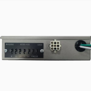
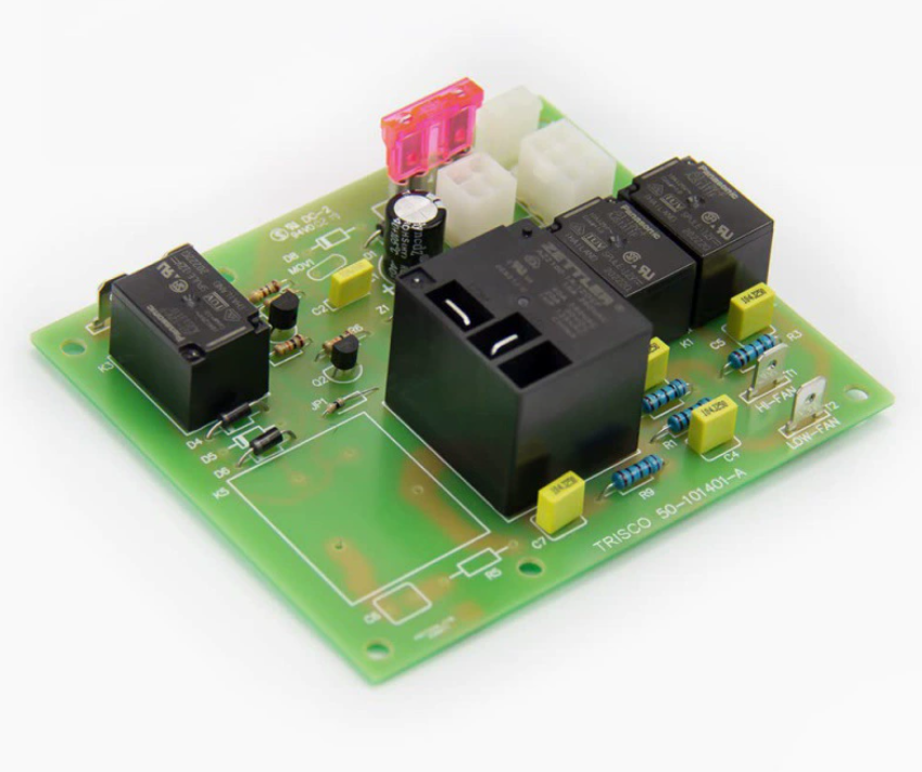
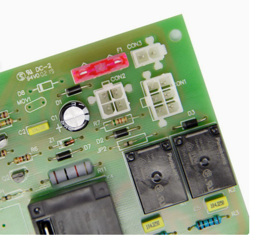
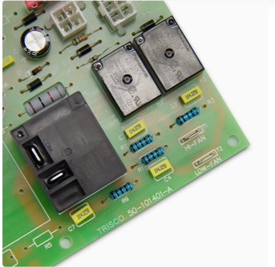
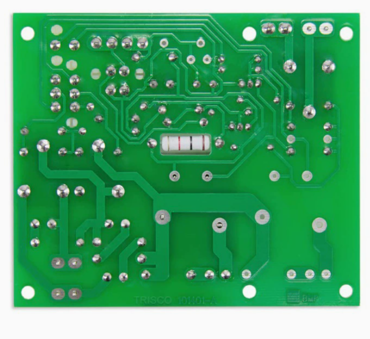
Dometic 3311924.000 Relay Board | Duo Therm Analog RV Air Conditioner Replacement
$25.00
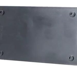
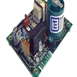
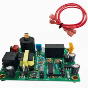
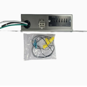
Dometic 3311924.000 relay board for Duo Therm analog RV air conditioners. Controls compressor, fan speed (high/low), and thermostat communication. Direct replacement for Dometic, Duo Therm & Brisk Air analog AC units. Plug-and-play, no programming. Free shipping.
Free shipping on orders over $60! Delivery time: 7-12 days
- Satisfaction Guaranteed
- No Hassle Refunds
- Secure Payments
Dometic 3311924.000 Relay Board – Duo Therm Analog RV Air Conditioner Replacement
The relay board (also called the control board or relay module) is the electronic component that manages the electrical functions of your RV air conditioner. It receives signals from the wall thermostat and controls the compressor relay, fan speed relay (high/low), and power distribution. When the relay board fails, your AC may not cool, the fan may not work, or the unit may not respond to thermostat commands at all.
This Dometic 3311924.000 relay board is designed as a direct replacement for Dometic and Duo Therm analog RV air conditioners. It features plug-and-play installation with no programming required — simply remove the old board and install the new one.
Compatibility
- Dometic Brisk Air (B57915, B59516, B59186, B59196)
- Dometic Brisk Air II (B57915.XX1C0, B59516.XX1C0, B59186.XX1C0)
- Dometic Penguin (600315, 600316, 600815, 600816)
- Dometic Penguin II (640315, 640316, 641815, 641816)
- Dometic Duo Therm (57915, 59516, 59186, 600315, 600316)
- Dometic ADB (Air Distribution Box) analog systems
- Most Dometic 13,500 BTU and 15,000 BTU analog rooftop AC units
- Replaces part numbers: 3311924.000, 3311924.005, 3109226.006, 3109226.011
- Works with Dometic analog wall thermostats (4-wire: cool, fan high, fan low, common)
Specifications
| Parameter | Specification |
|---|---|
| Part Number | 3311924.000 (replaces 3311924.005, 3109226.006) |
| Input Voltage | 120V AC, 60Hz |
| Thermostat Voltage | 12V DC (for thermostat communication, supplied by board) |
| Compressor Relay | 120V AC, 20A (SPST-NO) |
| Fan Relay | 120V AC, 10A (SPDT — high/low speed) |
| Fan Speeds | High, Low (2-speed fan control) |
| Modes | Cool, Fan Only, Off (analog thermostat control) |
| Thermostat Compatibility | 4-wire analog (cool, fan high, fan low, common/12V) |
| Connections | Plug-and-play wire harness (matches original) |
| Mounting | 4-screw mounting in ceiling assembly (matches original footprint) |
| Protection | Compressor delay (30-second anti-short-cycle), over-current protection |
| Operating Temp | -40°F to 140°F (-40°C to 60°C) |
| Certification | UL listed, CE, RoHS |
Installation Guide
- Safety first: Turn off 120V AC power at the circuit breaker. Turn off the generator if running. Also disconnect 12V power at the battery (the board supplies 12V to the thermostat). Allow the AC unit to cool completely.
- Access the board: From inside the RV, remove the air conditioner ceiling assembly (inner shroud) by removing the 4 mounting screws. Lower the assembly carefully. The relay board is typically mounted inside the ceiling assembly, near the wiring harness, behind a plastic cover.
- Document connections: Take detailed photos of all wiring connections before disconnecting. Label each wire connector with tape if needed. Note the position of each connector on the old board.
- Disconnect wires: Unplug all wire harness connectors from the old board. This typically includes: 120V AC power input, compressor output, fan motor output (high/low), thermostat wires (4-wire), and 12V DC power (for thermostat).
- Remove old board: Unscrew the 4 mounting screws holding the board to the ceiling assembly bracket.
- Install new board: Mount the new 3311924.000 board in the same position. Secure with the 4 mounting screws.
- Reconnect wires: Plug all wire harness connectors into the corresponding positions on the new board (refer to your photos). Ensure all connections are secure. Double-check the 120V power connections — black to hot, white to neutral, green to ground.
- Reassemble: Lift the ceiling assembly into position and secure with the 4 mounting screws.
- Test operation: Restore 120V AC power and 12V DC power. Set the analog thermostat to COOL mode, lower the temperature, and select fan speed. Verify: the fan starts (high or low as selected), the compressor starts after a 30-second delay, cool air is discharged, and the unit cycles off when the set temperature is reached. Test both fan speeds and FAN ONLY mode. Let the unit run for at least 15 minutes to ensure stable operation.
Common Symptoms of a Bad Relay Board
- AC doesn’t respond to thermostat commands at all
- Fan runs but compressor won’t start (no cooling)
- Compressor runs but fan doesn’t (can damage the compressor)
- Fan only works on one speed (high or low relay failed)
- AC runs continuously without cycling
- Clicking sounds from the ceiling assembly but no operation
- Burning smell or visible burn marks on the board
- Circuit breaker trips when AC is turned on
- Thermostat has no power (display blank on digital thermostats)
- Compressor short-cycles (turns on and off frequently)
Frequently Asked Questions
Q: How do I know if my relay board is bad or if it’s the thermostat?
A: To isolate the problem: (1) Check if the thermostat has power — for analog thermostats, you should hear a click when changing modes. For digital thermostats, the display should be lit. (2) Try jumping the thermostat wires at the relay board — connect the “cool” wire to the “common/12V” wire. If the compressor and fan start, the relay board is good and the thermostat is bad. If nothing happens, the relay board is likely bad. (3) Check for 120V AC power at the board input terminals. If no power, check the circuit breaker and wiring. (4) Check for 12V DC output from the board to the thermostat. If no 12V, the board’s power supply is bad.
Q: Can I use this board with a digital thermostat?
A: This 3311924.000 board is designed for analog (4-wire) thermostats. It can work with some digital thermostats that are compatible with analog 4-wire systems, but you may need an adapter or a different relay board for full digital thermostat functionality (such as programmable setpoints, digital display, or multi-zone control). If you’re upgrading to a digital thermostat, check the thermostat manufacturer’s compatibility requirements. Dometic offers specific relay boards for their digital thermostat systems (such as the 3314082.000 or 3316230.000).
Q: Do I need to program the new board?
A: No. This 3311924.000 relay board comes pre-configured and ready to use. Simply install it and connect the wires — no programming, dip switches, or calibration required. The board automatically detects your AC unit configuration based on the wiring connections. Just make sure you connect all wires to the correct terminals as documented from your old board.
Q: Why does my AC have a 30-second delay before the compressor starts?
A: The 30-second compressor delay (also called anti-short-cycle protection) is a normal and important safety feature. When the thermostat calls for cooling, the fan starts immediately, but the compressor is delayed by 30 seconds. This prevents the compressor from starting against high head pressure if the AC was recently turned off and back on (short-cycling). Starting a compressor against high pressure can cause excessive current draw, tripped breakers, and premature compressor failure. The 30-second delay allows the refrigerant pressures to equalize, ensuring a smooth, safe compressor start. This delay is built into the relay board and is not a malfunction.
Related Products
- Coleman Mach 15 AC Controller — Replacement controller for Coleman Mach air conditioners
- RV AC Parts Kit (3314998.000) — Safety limit switch and grille for Dometic AC
- 12V 13500BTU Rooftop AC Heat Pump — Complete 12V DC rooftop AC with heat pump
Need help repairing your Dometic Duo Therm air conditioner? Contact our technical team with your AC model number and symptoms. Free shipping and duties included.
You must be logged in to post a review.


Reviews
There are no reviews yet.